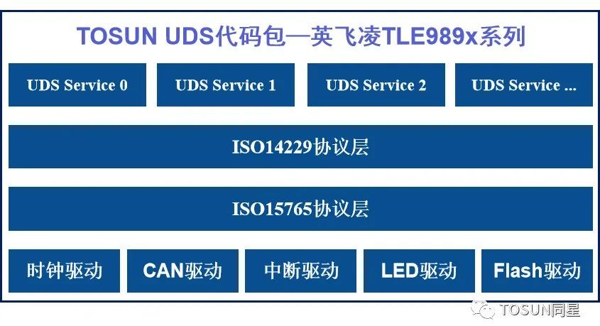
1. Program overview
TOSUN Technology provides customized developed code package and flashing tool for Infineon TLE989X series chips, mainly including code package, flashing project based on TSMaster, flashing hardware tool TF1011 and so on. With TF1011, you can directly flashing the Bootram without Infineon's own burner; you can also flashing the APP based on UDS.
With TF1011, you can directly flashing Bootram without Infineon's own burner; you can also flashing APP based on UDS.
❖ Code package contents
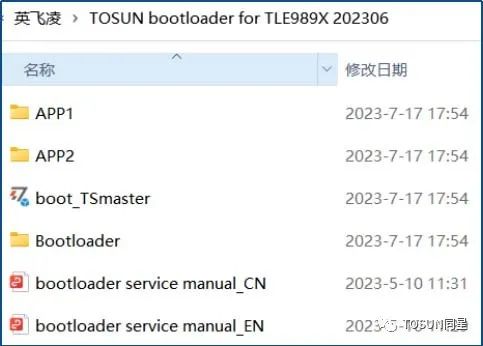
The code package provides APP1, APP2, Bootloader, boot_TSmaster, and usage documentation, among others:
- APP1 file and APP2 file are APP routines for LED blinking with different frequencies
- The boot_TSmaster folder contains the configured TSmaster software project routines, which can be used in conjunction with the Bootloader to realize the function of downloading the APP.
- The bootloader service manual is in English and Chinese.
- Inside the bootloader file is the bootload source code, which is shown below:
2. Based on the TSMaster configuration flashing process
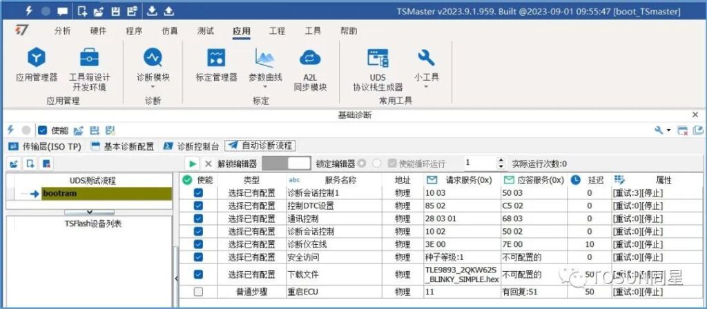
In our sample code, the flashing process is the following 10 steps:
Step1: 10 03 //10 service switch to 03 extended mode
Step2: 85 02 // turn off DTC (empty service, no specific implementation)
Step3: 28 03 01 // service shutdown message (empty service, no specific implementation)
Step4: 10 02 //10 service switch to 02 programming session
Step5: 27 01 // 27 Services, unlocked, pass security verification
Step6: 27 02
Step7: 2e 00 00
Step8: 31 00 00
Step9: (34, 36, 37) // Composite Diagnostic Services Download APP
Step10:11 //ECU reset
Configuring the flashing process in the TSMaster software generally goes through three steps:
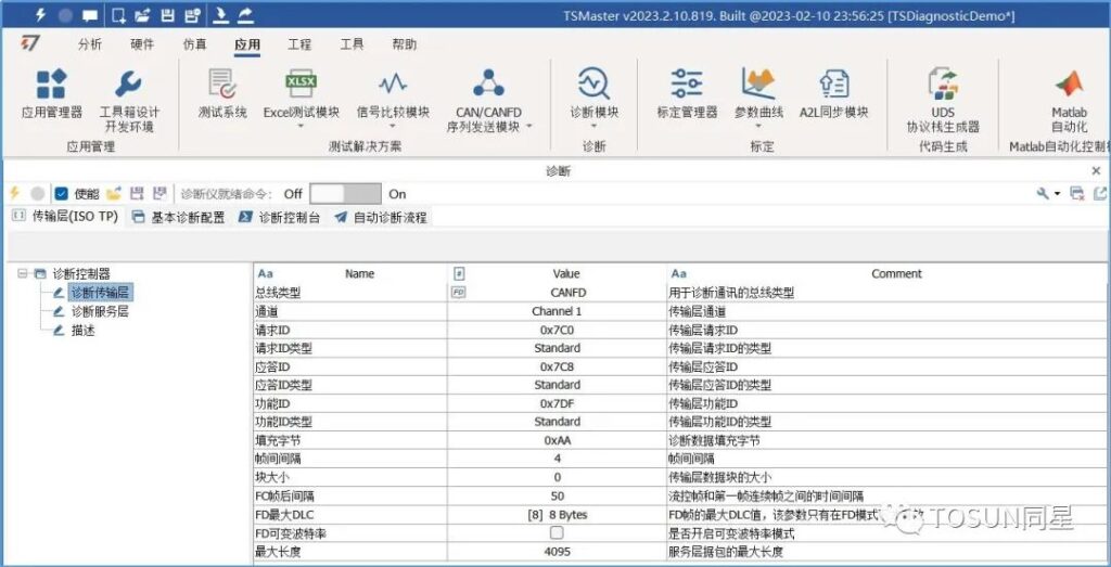
❖ Step 1: Configure relevant parameters
- Diagnose transport layer parameter configurations (bus type, various types of IDs, channel DLC, intervals, etc.)
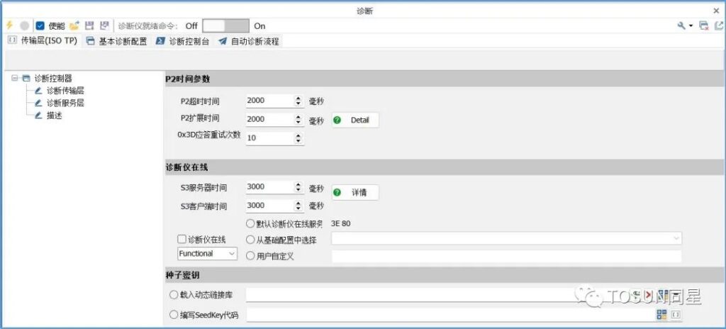
- Diagnostic service layer parameter configuration (P2 time parameters, diagnostic instrument online parameters, seed key)
.
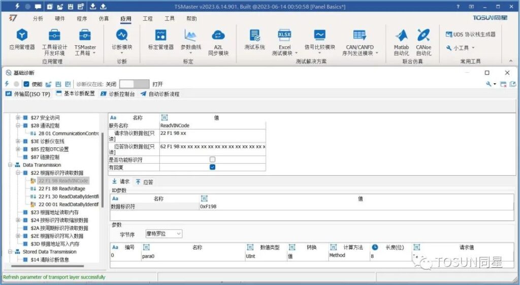
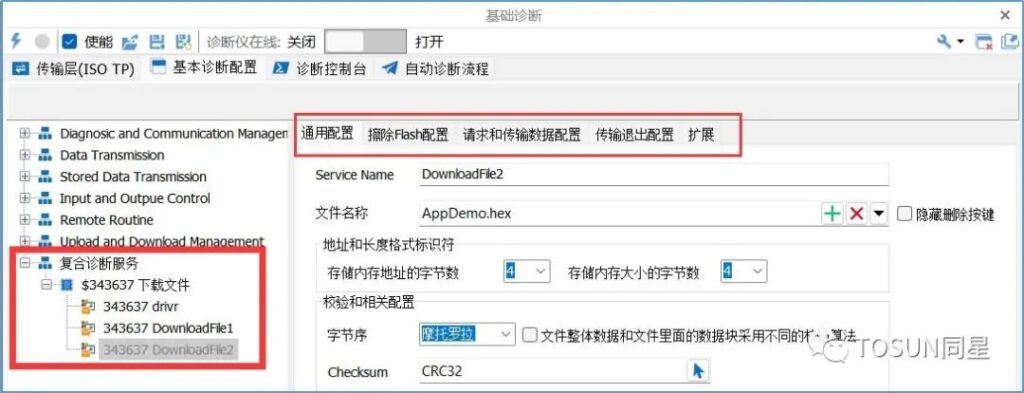
❖ Step 2: Configure Diagnostic Services
Configure here all the diagnostic services that will be used in our flashing process, as well as the composite diagnostic service (343637) that is used to download the APP. The composite diagnostic service contains the loading of the APP file, the configuration of the check method, the configuration of erasing the Flash, the requesting and transferring of the data configuration, and the transferring of the exit configuration, and so on.
❖ Step 3: Configure the flashing process
Configure in the auto-diagnostic process to configure the flashing process according to the steps we mentioned earlier.
After the configuration, you can use the CAN to USB CAN card to flashing online, or you can download this process to the offline tool TF1011 to realize offline flashing.
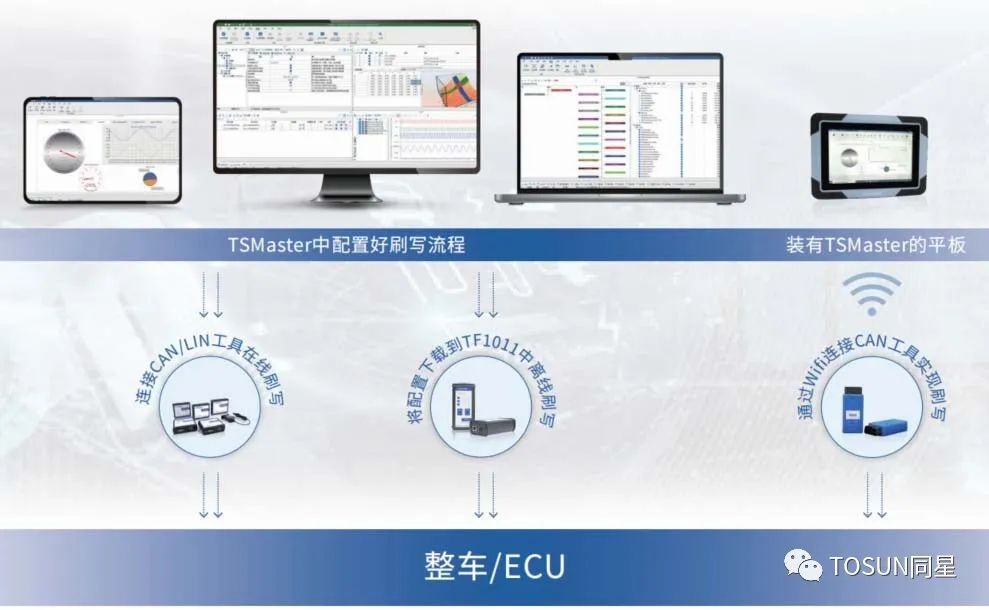
3. Flashing method
After configuring the flashing process, you can either connect to a PC with a CAN-to-USB CAN card to realize online flashing, or download this process to the offline tool TF1011 to realize offline flashing.
The advantage of online flashing is that if you use a multi-channel CAN tool, you can realize flashing multiple ECUs at the same time, and of course, you can also flashing multiple times in a row for stress testing of the flashing, etc.
Offline flashing is mainly used in production line or after-sales, the main portable.
The following table shows the tools that can be used to realize online flashing. Of course, we also have tools for LIN and Ethernet, and you can configure the flashing process of the LIN/Ethernet bus nodes directly in the TSMaster software in the same way as for CAN flashing.
Product Model | Device Description |
TC1011 | 1 CAN FD to USB interface |
TC1012/P | 1 CAN FD, 1 LIN bus to USB interface |
TC1013 | 2-way CAN FD to USB interface |
TC1014 | 4-way CAN FD to USB interface |
TC1016/P | 4-way CAN FD, 2-way LIN device to USB interface |
TC1017 | 8-way CAN FD to USB interface |
TC1018 | 12 CAN FD to USB interface |
MP1013 | 2 CAN FD to miniPCIe interfaces |
TP1013 | 2-way CAN FD to PCIe interface |
TC1114B | 4-Channel CAN FD to USB/WIFI |
The offline flashing tool is currently only available for the TF1011 with 1 CAN FD/CAN channel (the 4-channel version is still under development). The TF1011 supports the simultaneous configuration of three groups of download processes, which can be switched by pressing a key.
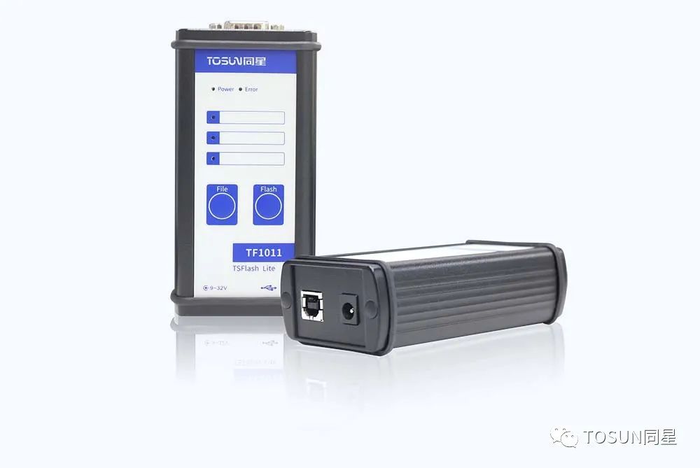
❖ TOSUN Technology TF1011
1 CAN FD interface, compatible with both CAN2.0 and CAN FD, with built-in programmable termination resistor, eliminating the need for external termination resistors.
❖ hallmark
- Adopt DB9 interface, support power from DB9 interface
- The UDS flashing process is configured through the TSMaster software GUI, no programming required
- Seamless integration of R&D and production configuration processes
- Support custom-seed key algorithm download
- Supports up to three sets of diagnostic (including FBL flashing) processes simultaneously, switchable by key
- Flashing process message record (optional)
- Support Infineon Uart on CAN protocol
- Support for controlling the power port of the downloaded device