LIN stands for Local Interconnect Network and is a low-cost serial communication protocol based on UART/SCI (Universal Asynchronous Receiver-Transmitter / Serial Communication Interface). It can be used in a variety of fields such as automobiles, home appliances, and office equipment.
This article focuses on a detailed tutorial on the operation process of the same star LIN master and slave node emulation functions and other functions.
I. Operation of the same star LIN master node simulation function
1、Hardware connection preparation
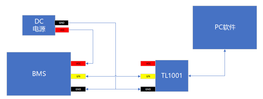
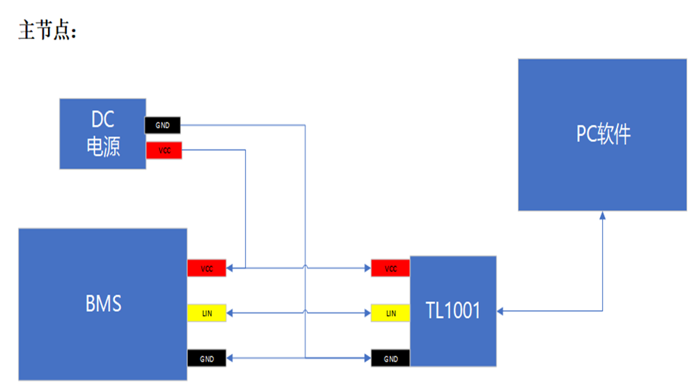
Using the same star LIN hardware simulation master node mode, external power supply is required, in order to keep the LIN bus level signal consistent with the measured parts, the connection schematic is as follows.
2、TSMaster software operation process
The following operation flow is exemplified by the TSMaster simulation LIN master node, and the measured part slave node is LED light.
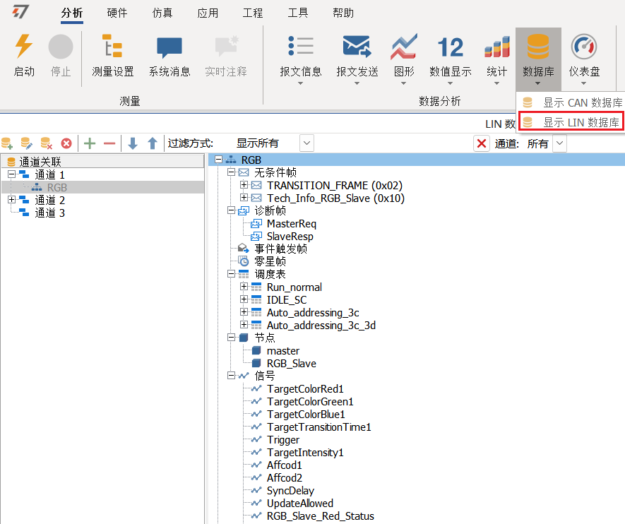
2.1 Importing LDF file database
After adding the LDF file of LEDs through the database, you can see that the [nodes] in the LDF file are [master] and [RGB_Slave] respectively, and contain the master node scheduling table information, message and signal definitions.
2.2 Create LIN send window and perform LIN master node configuration
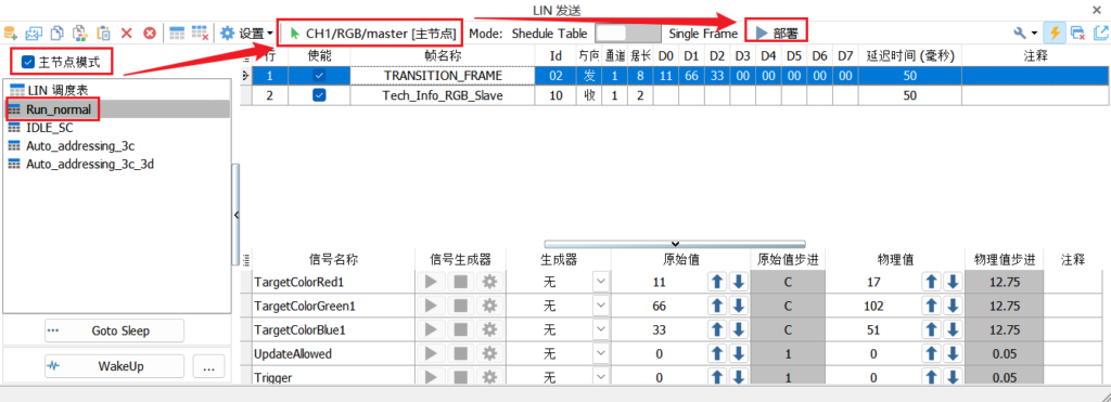
Check [master node mode], then select Run_normal for the run scheduling table and select emulation [master master node], you can see that two messages of the scheduling table are checked. At this time, you can [Deploy] run the scheduling table.
▲ [Note]: You need to pay attention to the sending direction of the master and slave node messages in the scheduling table.
Emulate the message direction of master master node: [send]
The direction of the message from the node response is: [Received]
That is, message 0x02 is a control message sent from the master node to the RGB slave node, so the direction is transmitting, while message 0x10 is for the RGB feedback from the slave node to the master node, so the direction is receiving.
2.3 LIN message information monitoring
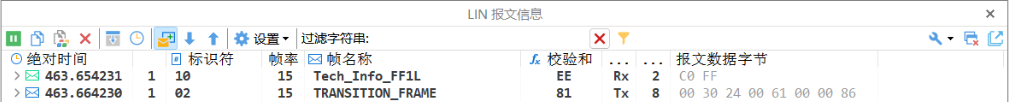
Under normal circumstances, after the scheduling table is running, the data contents of two messages can be viewed in the LIN message information window, indicating that the slave node is communicating with the master node normally and feeding back data.
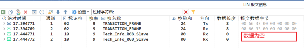
▲Non-normal situation: If the response data of the message from the slave node is empty, it can be judged that the slave node is not responding, at this time, you can check whether the LIN bus connection is correct or whether the power supply of the LIN slave node is normal, etc., as shown in the following figure
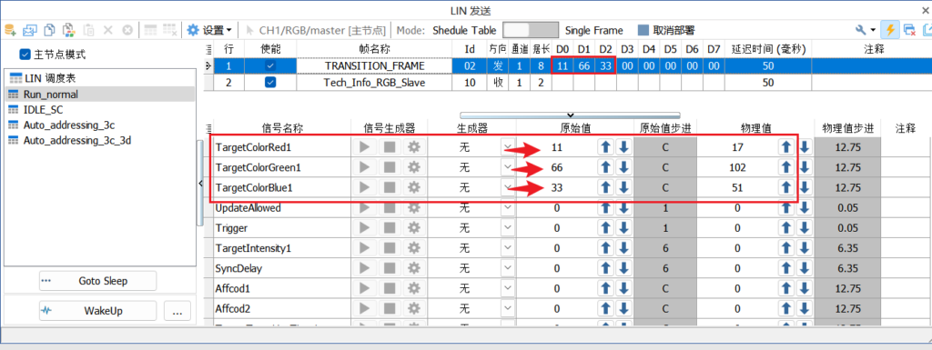
2.4 Modify the content of LIN master node control message
In the [LIN transmit window], select the master node message such as 0x02, you can directly modify the original value or physical value of the LIN signal to assign the message signal.
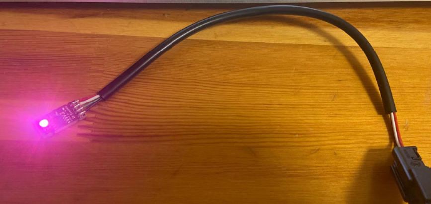
By modifying the signal values of the three different colors of RGB, the same light colors can be combined. The following figure shows the lighting of RGB lights for reference.
3. [Example 1] LIN diagnostic function - automatic address assignment
Usually before RGB lighting function test, it is necessary to auto-assign address to RGB lights before light color, brightness test, version number reading, etc. can be performed.
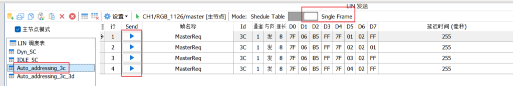
[Background]: According to the protocol of LIN automatic address assignment, multiple 3C diagnostic messages need to be sent for address assignment at a single time, and TSMaster is available through [Single Frame] mode.
The message for the automatic address assignment of RGB lights is as follows.
1. Single send: 7F 06 B5 FF 7F 01 02 FF
2. Single send: 7F 06 B5 FF 7F 02 02 01
3. Single send: 7F 06 B5 FF 7F 03 02 FF
4. Single send: 7F 06 B5 FF 7F 04 02 FF
[Hands-on]: Run the diagnostic command in [Single Frame] of TSMaster software, create the corresponding messages and send message lines 1, 2, 3 and 4 from top to bottom respectively to complete the automatic RGB address assignment.
4. 【Example 2】 The use of insert_lin_message function for inserting message frames
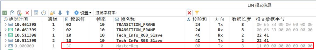
There is a common usage scenario to insert a frame of other LIN message, such as 0x3C message, when the emulation master node is running the scheduling table without stopping the running scheduling table, this function can be implemented by the inject_lin_message function.
Create a new C Script Editor and select [Keystroke Events], for example, create keystroke "A" to execute the insertion message.
Then compile and run the C script, and with the deployment schedule running, press the "A" key, and you can observe the 3C messages being sent in the LIN message message.
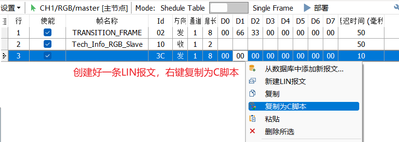
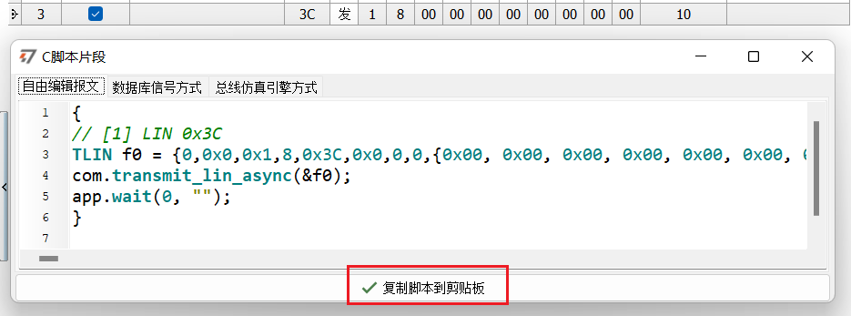
[TSMaster Software Tips - Quickly Generate C Code for LIN Messages]: You can create a new LIN message in the scheduling table and right-click to copy it as a C script to quickly copy the C code of the message to the script.
Second, the same star LIN slave node / listener node function operation
1. Hardware connection preparation
Emulation of slave nodes can be done without powering the same star LIN card.
2. emulate the slave node to send response messages
When the same star LIN card is emulated as a slave node, the ECU master node needs to send the header Header of the scheduling table for the slave node response message to be sent normally.
In this paper, the LIN channel 1 of TSMaster emulates the master node running the scheduling table, and LIN channel 2 emulates the slave node responding to message 0x10 (Tech_Info_RGB_Slave).
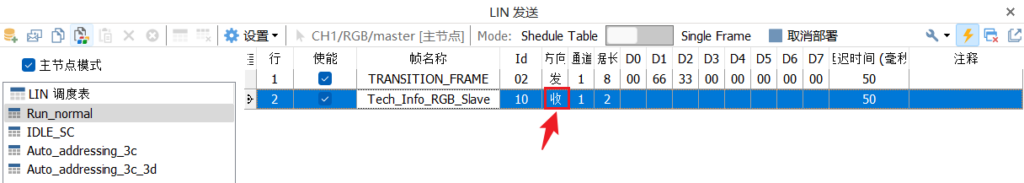
First, LIN channel 1 emulates the master node running the scheduling table, where the header direction of the response message from the slave node is [received].
After the deployment is running, you can see that the LIN slave node message header has been sent and the data is empty.
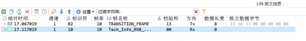
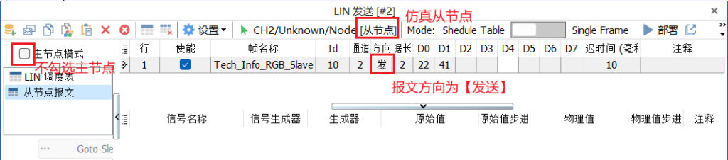
Then, the LIN channel 2 emulation slave node sends a response message 0x10 (Tech_Info_RGB_Slave) in the direction of [send], modifying the data content.
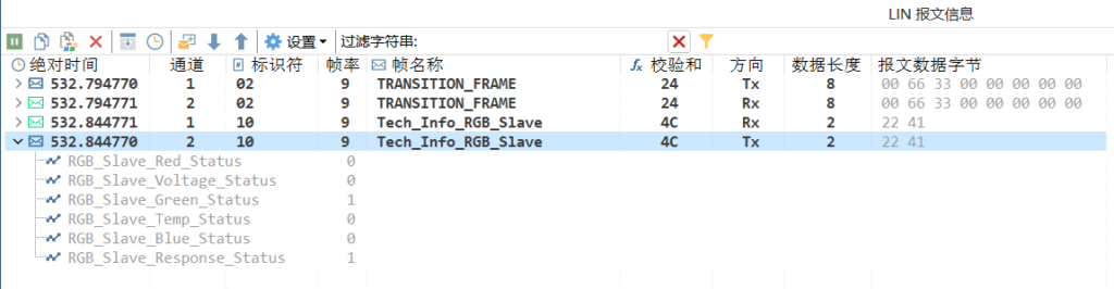
2 Click [Deploy], you can observe from the LIN message information that the slave node message 0x10 successfully sends a response message, and the master node also receives it successfully.
Beta version updated weekly, full version updated monthly
Installation environment
1
Windows 7 SP1 or higher, supports Win10, and WIn11.
Operating System
2
8GB
random access memory (RAM)
3
At least 550MB of free space
disk space
4
Dual-core (2-core) or higher
CPU
Please ensure that your computer meets at least these requirements in order to install and run the TSMaster software successfully. If your computer does not meet these requirements, it may cause performance problems or not run the software properly. You may want to consider upgrading your hardware if you need smoother running features.