The full name of RBS is: residual bus simulation, which is also known as residual bus simulation. It is mainly based on the in-vehicle network database, such as CAN/LIN/FlexRay/Ethernet database, and simulates the communication behavior of each node within the network.
This article mainly explains the operation procedure of LIN RBS in TSMaster.
Catalogue
Catalog
一. Hardware connection preparation
Second, TSMaster software LIN RBS operation process
1、Import LDF file
2、 LIN channel selection
3、Configure LIN bus emulation
3-1. LIN master-slave node activation
3-2. Description of configuration items
4、Modify the signal value of the RBS simulation node
4-1. LIN Remaining Bus Simulation Modification
4-2. Combining C scripts to modify signal values
4-3、Modify the signal value with the panel
一. Hardware connection preparation
Hardware connection preparation
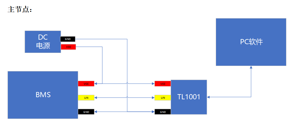
To first connect the same star LIN hardware, use the same star LIN hardware simulation master node mode, external power supply is required, in order to maintain the LIN bus level signal with the measured parts, the connection schematic is as follows:
▲Note: If using the TC1012P, TC1016P, and TC1026P, which are USB-powered models, no external power supply is required.
二. TSMaster LIN RBS operation process
TSMaster LIN RBS OPERATION PROCESS
1、Import LDF file
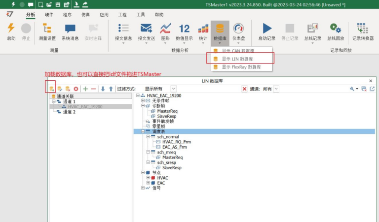
Load the ldf file through [Database], you can also directly drag the ldf file into TSMaster. You can view the nodes in the LDF file, where the nodes marked in red are the master nodes, and the database contains the node scheduling table information, messages and signal definitions:
2、LIN channel selection
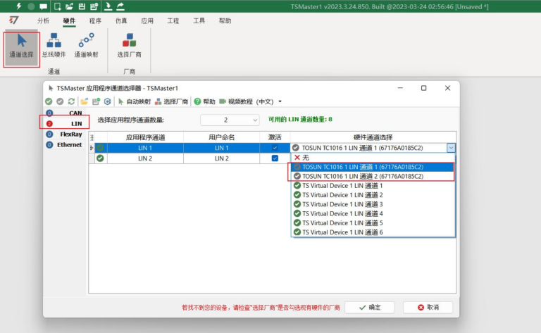
Check LIN in the hardware bar [Channel Selection], select the number of [Application Channels], then there is a drop-down option at the channel selection to select the real hardware channel with the hardware name and serial number (as shown in the figure for TC1016):
3、Conduct LIN bus emulation configuration
3.1 LIN master-slave node activation
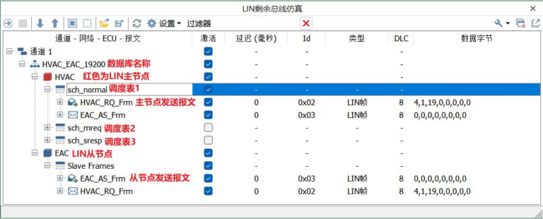
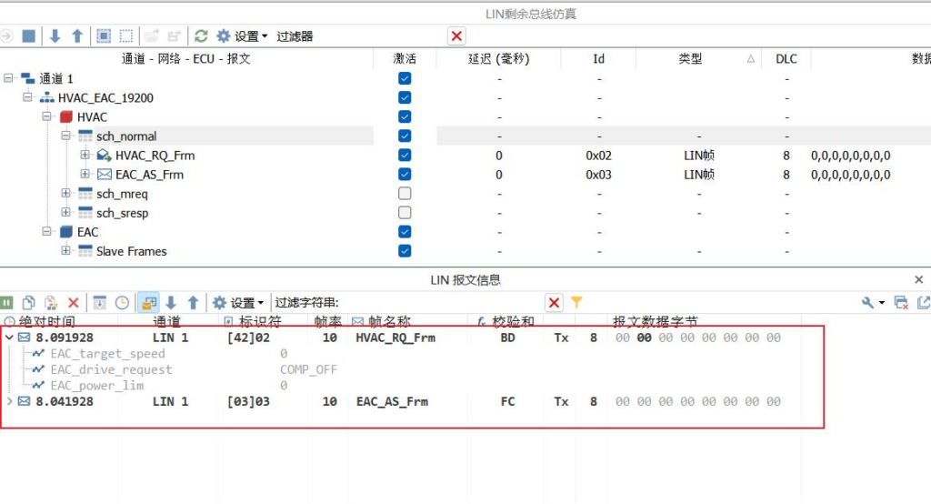
Open the LIN bus emulation module via [Emulation] -> [LIN Bus Emulation]. In the LIN residual bus emulation, you can view the channels that have been bound to the database with network, node, scheduling table and message activation checkbox options.
The node in red is the master node such as HVAC. After checking Activate Network->Node->Scheduling Table here, you can emulate this node by RBS. After starting the emulation, you can view the message sending and receiving information in the node in the message information window.
3.2 Description of configuration items
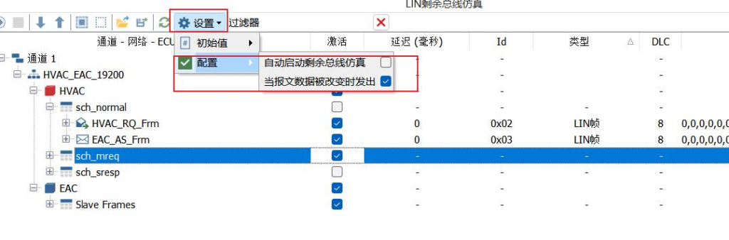
The RBS module of TSMaster mainly contains the following configuration items:
Auto-start residual bus emulation: If enabled, the residual bus emulation module is automatically started when the application is connected.
Automatically send the message where the signal is located when the signal is changed: If enabled, this message is sent immediately when the signal is modified.
4. Modify the signal value of the RBS simulation node
4.1 LIN residual bus simulation modification
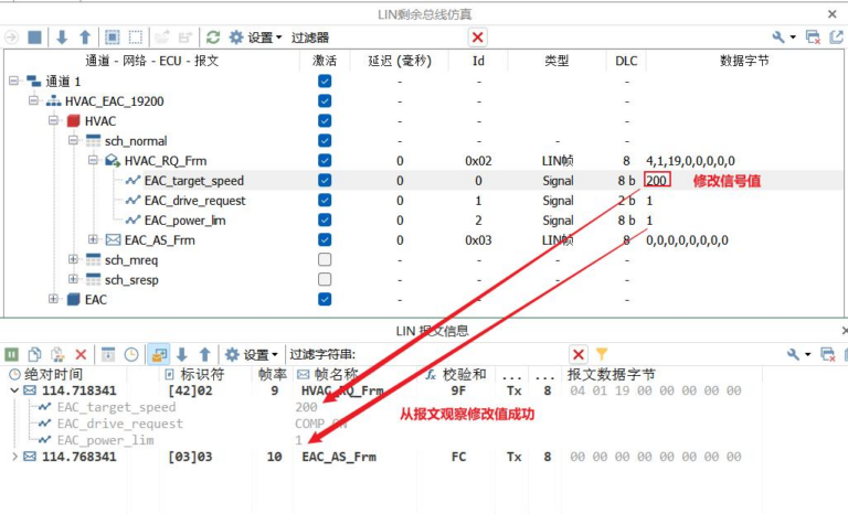
After checking the network nodes to be emulated and the scheduling table, expand the scheduling table -> Messages -> Signals, you can see the signal value of the current emulated signal in the data byte column of the signal, and change the emulated signal value by directly entering here:
4.2 Modifying signal values in combination with C scripts
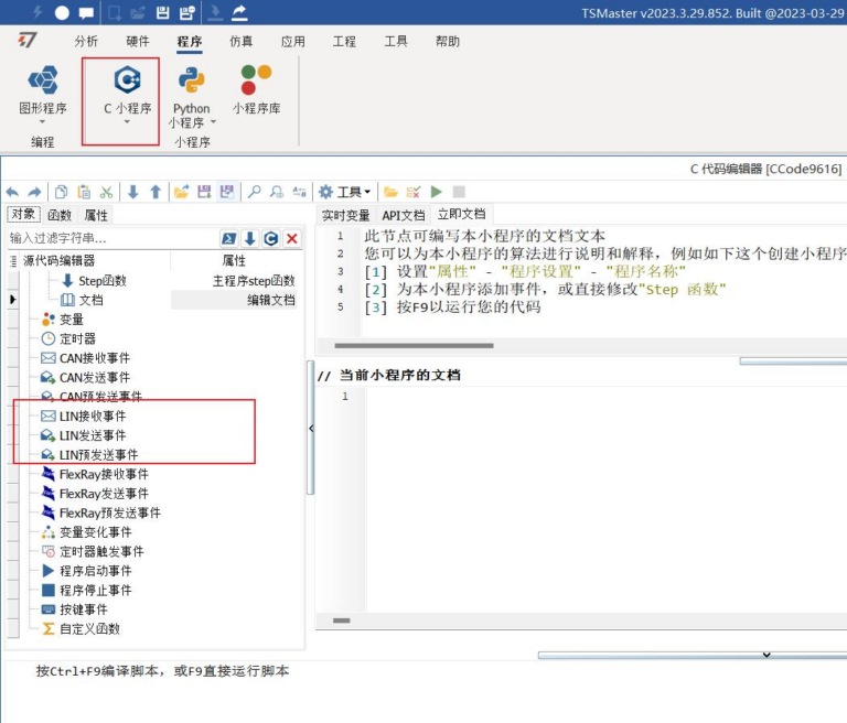
After the RBS module is configured, open a c applet module and you can see that there are LIN-related receive/transmit/pre-send events, which currently need to be assigned to the signal values in the bus emulation, as follows:
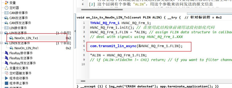
1) First create the LIN transmit event and pre-send event for the message, define the message to be signaled in the LIN transmit event, and then send the message using the transmit_lin_async function, mainly to trigger the LIN pre-send event:
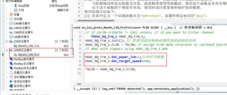
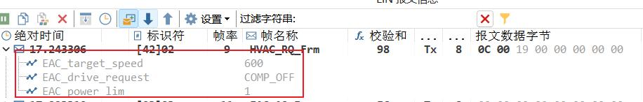
2)Once the pre-send event is triggered, you can assign a value to the signal directly in the pre-send event, compile and execute the script after the assignment, and you can see in the message window that the value of the signal has changed:
4.3 Modify the signal value in combination with the panel
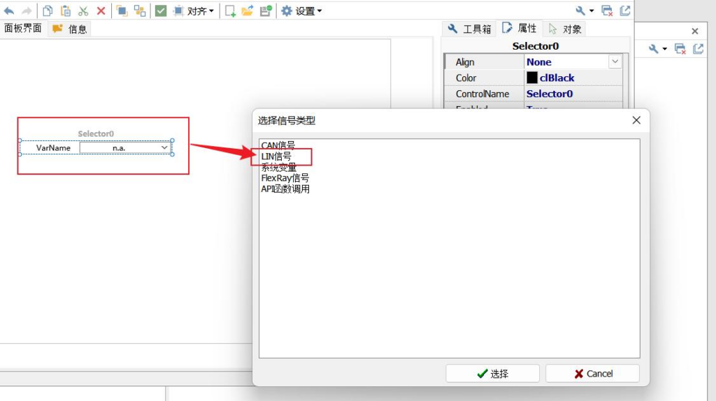
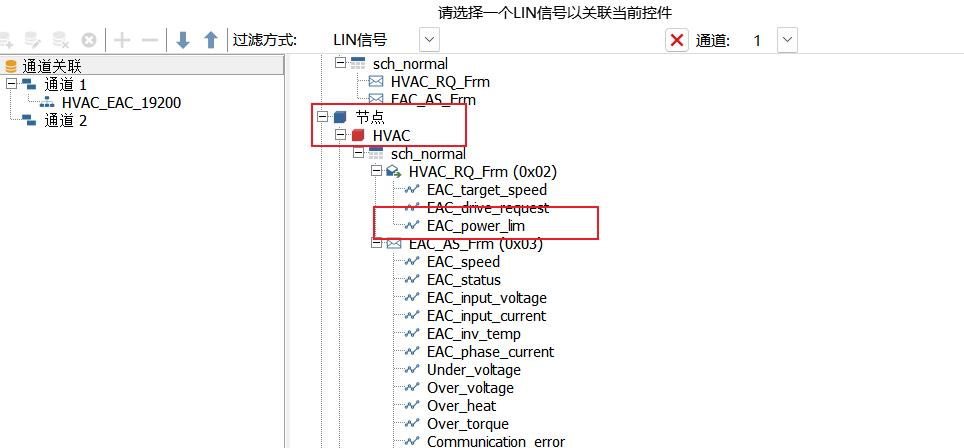
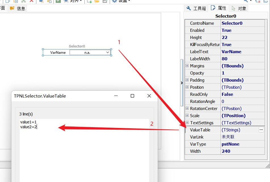
1) First create a panel in [Simulation] -> [Panel], create an input control, here use the selector, double-click the control to select the LIN signal (Figure 1), and then find the signal that sends the message under the simulation node to bind (Figure 2).
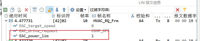
2)Once the pre-send event is triggered, you can assign a value to the signal directly in the pre-send event, compile and execute the script after the assignment, and you can see in the message window that the value of the signal has changed:
Beta version updated weekly, full version updated monthly
Installation environment
1
Windows 7 SP1 or higher, supports Win10, and WIn11.
Operating System
2
8GB
random access memory (RAM)
3
At least 550MB of free space
disk space
4
Dual-core (2-core) or higher
CPU
Please ensure that your computer meets at least these requirements in order to install and run the TSMaster software successfully. If your computer does not meet these requirements, it may cause performance problems or not run the software properly. You may want to consider upgrading your hardware if you need smoother running features.