overviewPreface
A. Process use case management
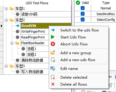
❖ It mainly contains the following operations:
[1] Add a new group: Add a new diagnostic process group, such as model 1. For example, add a new model 1. Diagnostic process use cases can be added under the diagnostic group, which itself does not contain diagnostic steps.
[2] Add a new uds flow: add a new diagnostic flow use case, under the diagnostic flow use case you can add detailed diagnostic steps.
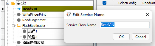
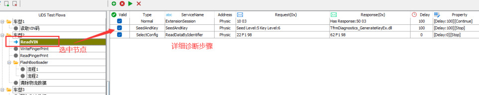
【3】Edit name: Select a process group or process use case, right click and select Edit name to edit the name of the node, as shown in the following figure:
[5] Start Uds flow: Start the diagnostic flow of this node. After clicking this option, the diagnostic module automatically executes the diagnostic steps from top to bottom according to the configuration on the right.
[6] Abort Uds flow: Click on this node to interrupt the diagnostic flow steps being executed.
【7】 Delete selected: Delete the selected node.
【8】 Delete all flows: Clear all nodes.
B. Configuration Diagnostics Flow (UDS Flow)
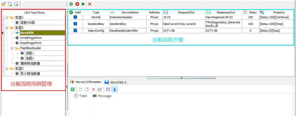
❖ B-1 Basic configuration steps:
Configure the diagnostic process with the basic steps shown below:
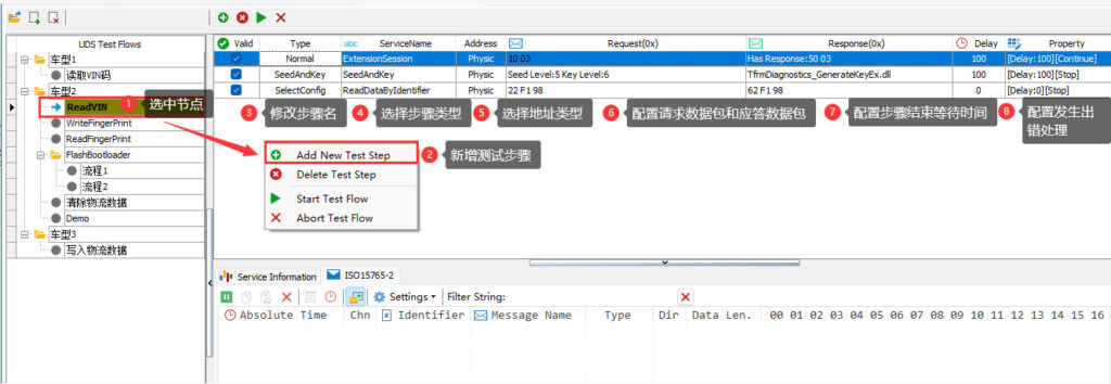
[1] Select a diagnostic process node in the left management column.
[2] Add, delete, and edit diagnostic steps in the edit area on the right.
[3] After adding a step, edit the step name.
[4] Select the type of step.
[5] Select the type of address for this step, physical address or functional address.
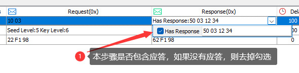
[6] Configure detailed diagnostic request packets and answer packets.
[7] Configure the wait time between steps after this step.
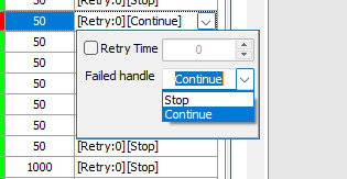
[8] Configure the error handling method when an error occurs in this step.
❖ B-2 Toolbar:
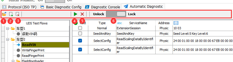
[1] Added a new diagnostic process group.
[2] New diagnostic process use cases have been added.
[3] Delete the selected diagnostic process group/use case.
[4] Start the configured diagnostic process.
[5] Interrupt the running diagnostic process.
[6] Lock/unlock the process configuration area. If this area is locked, it becomes uneditable in the diagnostic process area.
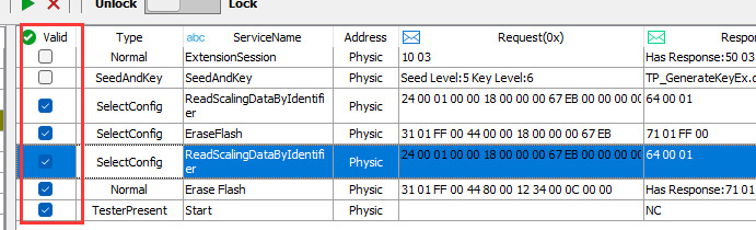
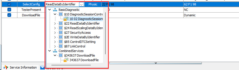
❖ B-3 Type of diagnostic step:
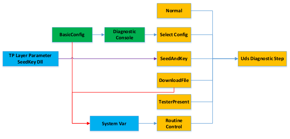
In order to increase the flexibility of diagnostic configuration in the test step, five types are designed for selection, as shown in the figure below, mainly including: Normal, SelectConfig, SeedAndKey, DownloadFile, TesterPresent, RoutineControl. through these five types, basically covers the market, basically covers all the mainstream diagnostic process requirements, the following detailed description of the characteristics of each type.
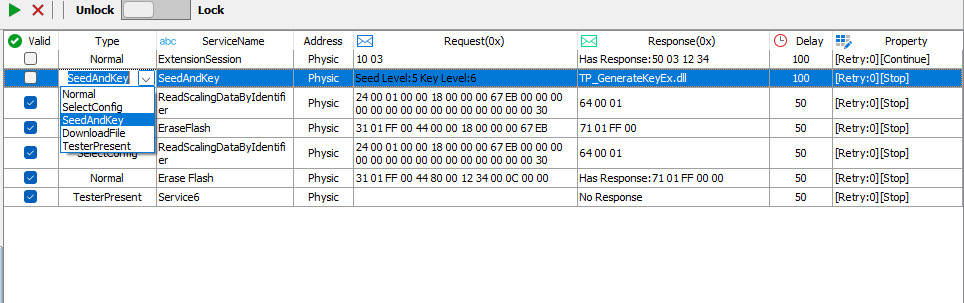


[3] SeedAndKey: SeedAndKey is a combination of commands, which can not be configured directly with the Normal command. Users can SelectConfig directly from the existing configuration, but also by selecting the type of SeedAndKey, in the automatic process directly configure the decryption steps. SeedAndKey only need to select the SeedLevel parameter can be decrypted DLL is directly associated with the TP parameter configuration loaded in the SeedAndKey in the Dll. As shown in the figure below:
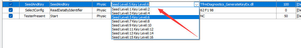
As you can see, the prerequisite for correct operation in either the Diagnostic Console module or the Automatic Diagnostic module requires that the user has correctly completed the configuration of the TP layer parameters.
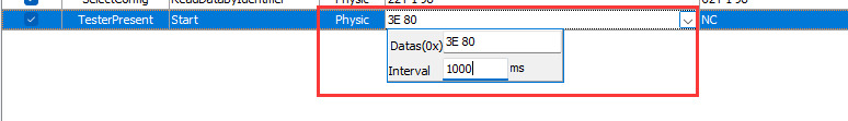
[4] TesterPresent: As mentioned earlier, TSMaster provides a global switch for TesterPresent, through which users can directly turn the command on and off. At the same time, in order to support more flexible testing needs, in the automation process steps, also provides a step-based configuration of the command, allowing users to choose to turn on and off the TesterPresent command at the desired step. After selecting this type, there are two main parameters to configure:
Whether to start/stop the command is as follows:

[Diagnostic step-by-step configuration summary]
To summarize the configuration flow of the test steps in the previous section, the logical flow is composed as shown below:
❖ B-4 Step interval:

❖ B-5 Error handling:
❖ B-6 Enable step/position adjustment: