overviewPreface
A. Transport layer parameters
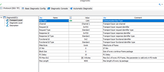
❖ The parameters are explained below:
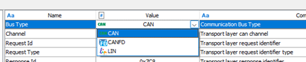
TheBus Type: Diagnostic Transport Layer Type, currently CAN/CANFD/LIN is supported, Ethernet and Flexray etc. are supported next. It can be selected through the drop-down list as shown in the figure below:
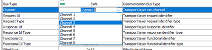
TheChannelTSMaster supports multiple diagnostic modules working online at the same time, this is used to select which logical channel of the system is used by the current diagnostic module. The selection is made through the drop-down list, as shown in the following figure:
TheRequest ID/Response ID/Function ID: Sets the ID of the diagnostic request/response/function frame for the PC tool side of the diagnostic module.
TheRequest ID Type/Response ID Type /Function ID Type: Set the ID type of the diagnostic request/response/function frame for the PC tool side of the diagnostic module, whether it is a standard frame (11-bit) or an extended frame (29-bit), as shown in the following figure:
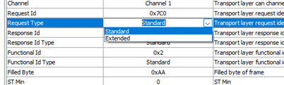
TheFilled Byte: During transmission, when the actual valid bytes are less than the data end of a CAN message, the filler bytes of the remaining data segments. For example, a frame CAN message 8 bytes, if the effective transmission byte is [0x02, 0x10, 0x02], filler byte is 0xAA, then the actual message byte is [0x02, 0x10, 0x02, 0xAA, 0xAA, 0xAA, 0xAA, 0xAA].
TheSTMin: Minimum Receive Interval. the minimum time interval between diagnostic frames that the TSMaster Diagnostic Module, as a receiver, can support when receiving consecutive frame messages, this parameter is replied to the diagnostic client. This parameter is set to 0 to support receiving at the shortest time interval.
TheBlockSize: The size of the receiving Block. the size of the block of data that the TSMaster diagnostic module, as the receiver, can receive at one time when receiving consecutive frame messages. This parameter is replied to the diagnostic client. Setting it to 0 means that it can receive any size of data block at one time.
TheFD Max DLC: When the transport layer is set to CANFD. At this time, the maximum number of bytes transmitted in a single frame of the transmission layer is 64 bytes (DLC=15), but this parameter can be adjusted, the range of adjustment is shown below:
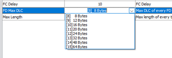
TheMax Length: This parameter is meaningless for normal CAN/LIN. For multi-frame transmission. When the DLC length = 8 bytes, the first frame (First Frame) adopts the lower four bits of the 0th byte + the 8 bits of the first byte, a total of 12 Bit to indicate the size of the packet to be transmitted at one time, that is, a maximum of 4095 bytes, as shown in the figure below:

However, in FDCAN, when setting the DLC length > 8 bytes, more Bits can be used to transmit the information. Therefore, the transmission layer of FDCAN supports the use of the 2nd, 3rd, 4th, and 5th bytes, totaling 32 bits, to transmit the length of a data block. In other words, FDCAN's transport layer supports the transmission of up to 4 gigabytes of data at a time. However, the exact amount of support is user-configurable.

Note: The high four bits of the first byte = 1, indicating that the frame is the first frame (First Frame), both for the FDCAN and Class CAN transport layers.
For example, if you configure bit 4095 bytes as shown below, it is the same as the normal transport layer. If it is configured to be greater than 4095, the transport layer with FD frame expansion is to be used.

B. Service layer parameters
❖ The parameters are explained below:
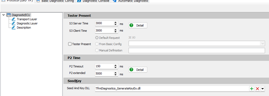
TheS3 Parameters: Includes S3 ServiceTime and S3 Client Time.
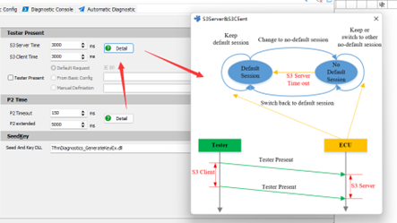
S3 Service Time: Indicates the timeout period after which the ECU will automatically switch back to the default session after it has been switched from the Default session to another session for a number of sessions.
S3 Client Time: Indicates the time interval for sending TesterPresent frames as the diagnostic Tester side.
A schematic of the above two parameters can be viewed by tapping on the Detail button and viewing the graphical illustration as shown below:
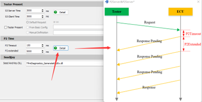
TheP2 parameters: Includes the P2 Timeout and P2 Extended parameters.
P2 Timeout. Indicates the minimum time interval for the ECU to reply after receiving a diagnostic request frame. For the diagnostic tool, this parameter can be used as a timeout judgment parameter for waiting for a reply after sending a request. For example, if the diagnostic tool sends a diagnostic message and does not receive a reply within the P2Timeout period, the request is considered to have failed and the timeout period exits.
P2 Extended:When the diagnostic tool sends a diagnostic message, the ECU under test is too late to respond within the P2 Timeout period, then it replies with a frame 3F XX 78 message to tell the diagnostic tool that it is too late to respond and needs to extend the waiting time before replying. after the ECU sends a delayed waiting message, then it switches the Waiting Time parameter to P2Extended. timeout judgment parameter on the diagnostic tool side After receiving the delayed wait message, you need to switch to P2Extended.
The above two parameters are schematically shown below:
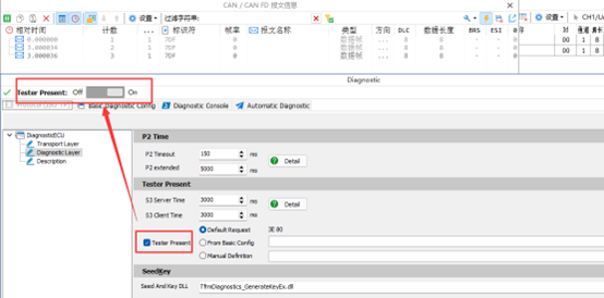
TheEnabling the Tester Present Command::
The TSMaster Diagnostics module has the option to configure and enable the TSMaster Present command as shown below:
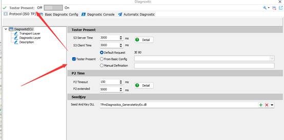
When this command is enabled, a switch to enable the Tester Present command appears at the top of the module. When Tester Presnet is turned on, the message is sent at the set S3ClientTime interval.
Tester Present's send byte is optional. Three types are supported:
[Default Request]: That is, the most commonly used 0x3E 0x80
【From Basic Config】:Select the configured 3E command from Basic Config.
[Manual Definition]: Bytes for customization
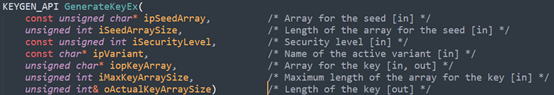
TheLoad Seed&Key DLL
In the diagnostic process, it will be designed to secure access to the problem, which is also known as Seed&Key. TSMaster diagnostic module supports loading the Seed&Key algorithm through the dll, the algorithm dll is compatible with the mainstream tools of the computational interface, the interface definition is shown in the following figure:
The DLL loading screen is shown below:
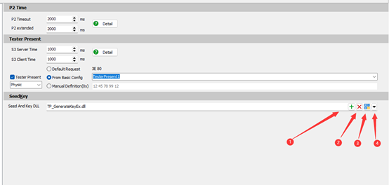
[1] Load DLL
[2] Delete DLL
[3] DLL Checker, through this button, users can determine whether the dll interface they loaded is correct and whether the algorithm meets the design requirements. As shown in the figure below:
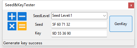
As shown in the above figure, the user selects the Level of Seed, inputs the value of Demo Seed, and clicks GenKey for judgment. If the interface of the DLL is unified with the interface defined in the template, a message will be output: Generate Key Success, and then the user will compare the key value with the target value to further confirm whether the algorithm in the DLL meets the design requirements.
[4] Open the path where the Seed&Key interface project is located in the TSMaster installation directory. Users can copy this project to add their own Seed&Key algorithm.
C. Tester Present