When the mismatch of sample point parameters and baud rate parameters between communication nodes causes some error frames, how can we set and adjust the baud rate parameters and sample point parameters in TSmaster to reduce and eliminate the error frames on the bus and further improve the communication quality. This article focuses on how to use TSmaster to get the corresponding sample point parameters and baud rate parameters more conveniently and set them to the user program through the API.
Keywords for this article:Sample point, baud rate, error frame, tsapp_configure_canfd_regs
The sampling point is the point in time when the CAN controller reads the bus level and interprets the logical value of each bit. Before we understand the sampling point, we need to understand the concept of bit time in CAN messages and the components of bit time. Bit time refers to the time required to transmit each bit of data, while the minimum time period of the CAN controller is called Time Quantum (TQ), which is obtained by dividing the frequency of the chip crystal period. A bit time consists of a number of TQs (usually 8 to 25), and at the same time, depending on the function, it can be divided into four phases: synchronization segment, propagation segment, phase buffer segment 1 and phase buffer segment 2.
The four phases function as follows:
● Synchronization Segment: Used to implement timing adjustments, the hopping edge of each node on the bus is generated within the synchronization segment, usually 1 TQ.
● Propagation Segment: Used to compensate for physical delay times on the network that incorporate signal transmission delays on the bus and processing delays within the CAN node.
● Phase Buffer Segment 1 (Phase_Seg1) and Phase Buffer Segment 2 (Phase_Seg2): are used to compensate for phase errors along the hopping edge, and their lengths are lengthened or shortened during the implementation of resynchronization.
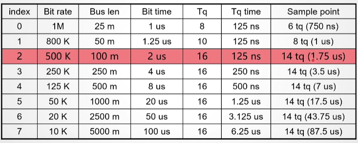
The share of sampling points and bit times corresponding to different scored baud rate times in CAN communication varies. Common sample points and related parameters are shown in the table below. Taking a baud rate of 500K as an example, a bit time is allocated into 16 time shares and the sampling point is in the 14th time share.
Suitable sampling point location is the guarantee of CAN controller's normal communication, and its importance has three main points as follows:
● For the CAN network as a whole, each node should try to use the same sampling point location, otherwise it is easy to have sampling errors, which will cause the communication of the whole network to malfunction;
● Sampling too early for a single node makes the node susceptible to level fluctuations at the beginning of the bit time, which in turn leads to sampling errors;
● The CAN controller cannot sample too late due to resynchronization requirements and the width of the phase buffer segment.
II. Communication problems due to sampling points
The CAN network uses asynchronous communication, so it needs to be sampled according to the baud rate, and the sampling principle is shown in the figure below. The red arrow indicates the location of the sampling point, and the sampled data is "1010 1010".
If the sampling point is set to 20% in advance, the data obtained after sampling is "0101 1010", which is not the same as the fifth bit of data obtained by sampling in Figure 4 when compared with the data in Figure 1. Therefore, in the CAN communication network, if the sampling point difference between the transmission nodes is different, it will cause the data transmission error, and as more data is transmitted, the more erroneous data bits are accumulated. Therefore, it is necessary to set the baud rate and sampling point of each node with the same bit when performing CAN network communication.
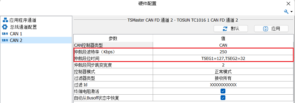
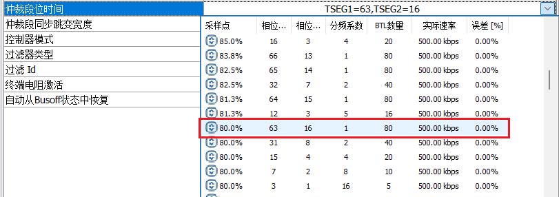
In a CAN communication network, the mismatch of baud rate and sample point settings between nodes leads to problems mainly in the form of error frames. Taking baud rate 500k, sampling point 80% (phase buffer segment 1 is 63, phase buffer segment 2 is 16) and baud rate 250k, sampling point 50% (phase buffer segment 1 is 3, phase buffer segment 2 is 4) as an example, the test is carried out by using the same-star hardware TC1016 and TSmaster, respectively, and the above parameters of baud rate and sampling point are deployed to the shorted CAN1 and CAN2 channels respectively.
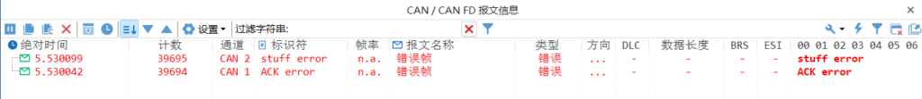
Under the condition of this parameter configuration, send a message in the message sending window of TSMaster, and then you can see the status of the message data transmitted on the bus under the message information window. As shown in the figure below, if the baud rate and sampling point parameters are configured differently between the communication nodes, an error frame will appear in the message information window.
Therefore, checking the baud rate and sampling point parameter configurations between nodes is a key direction to investigate when error frames appear in the TSMaster message information window. In addition, not only the error frame types shown in the above figure, but also other error frame types, such as bit error, form error, etc. (as shown in Figures 8 and 9), need to check the baud rate and sample point sampling point parameter configurations.
III. How to adjust the sampling point in TSMaster
When error frames are observed in the message information window of TSMaster due to improper sampling point settings, the parameter configurations in TSMaster need to be readjusted to achieve normal communication between nodes. Therefore, it is especially important to know how to adjust the sampling point and baud rate parameters in TSMaster to eliminate the error frames and improve the communication quality. But before that, one needs to know how to calculate the sampling point.
Where TSEG1 and TSEG2 are represented in TSmaster as phase buffer segment 1 and phase buffer segment 2, respectively. after knowing the formula of the sampling point, the corresponding sampling point parameters can be accurately calculated according to the communication parameters of the measured parts, and then the corresponding parameters can be further configured in the Bus Hardware Interface of TSmaster in order to realize the normal communication between nodes.
Procedure for adjusting the sample point and baud rate parameters:
● Step 1: First, you need to select the corresponding hardware channel in the channel needs to be selected screen and click Confirm.
Step 2: After determining the channel, configure the baud rate parameters in the bus hardware interface.
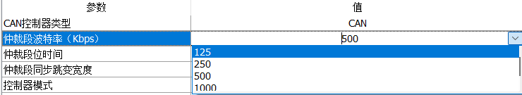
Take the CAN communication network as an example, the baud rate selection range is from 125kbps to 1000kbps, the baud rate selection should refer to the communication parameters of the DUT, and the baud rate parameter setting in TSmaster should be corresponding to it, if you don't know the baud rate parameter of the DUT, you can ask the manufacturer or switch to other baud rate parameter for the communication to see if it can improve the error frames under the other baud rate parameter. If you do not know the baud rate parameters of the device under test, you can ask the manufacturer or use other baud rate parameters for communication to see if the occurrence of error frames can be improved under other baud rate parameters.
TSMaster provides a number of sample point parameters for configuration purposes. Referring to the arbitration segment time option in the bus hardware interface, the same sampling point may correspond to different phase buffer segment 1 parameters and phase buffer segment 2 parameters, therefore, when selecting the sampling point, you need to use the sampling point formula to calculate the sampling point parameters by selecting the corresponding phase buffer segment 1 parameter and phase buffer segment 2 parameter according to the communication parameters of the DUT and then calculate the sampling point parameters.
In addition, when the sample point parameters calculated from the DUT or the phase buffer segment 1 and phase buffer segment 2 parameters cannot be found in the Arbitration segment time parameter option list, you can select a similar parameter in the option list to configure it. If the user does not know the communication parameters of the DUT, it is recommended to use the default sampling point parameters in TSMaster.
IV. tsapp_configure_canfd_regs parameter configuration
TSMaster provides many API functions for users to carry out secondary development, through which they can write user programs to realize various functions more in line with their own needs. When the communication error occurs in the secondary development program, the above method can be used to continuously adjust the configuration of the sampling point and baud rate and other parameters in the TSMaster interface, in order to improve the situation of error frames appearing in the bus, and then obtain the sampling point and baud rate and other parameters that are more in line with the communication with the measured parts.
The tsapp_configure_canfd_regs function serves to configure the internal registers of the CANFD controller to make the controller's sample points, synchronization jump widths, and other parameters more accurate. The function is shown in Figure 15:
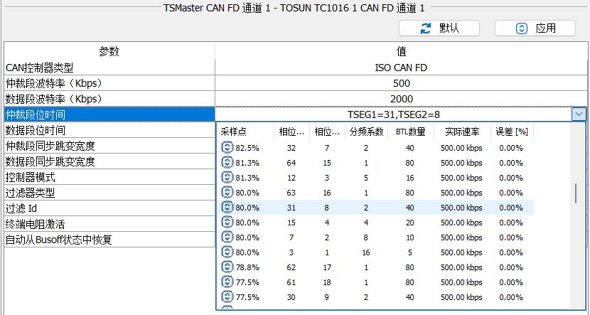
The above parameters may seem cumbersome, but you can directly view the corresponding parameter values through TSMaster's configurator. Take Arbitration Field 500k, Arbitration Sample Point 80%, Data Field 2000k, Data Field Sample Point 80% as an example. Enter TSMaster and open the bus hardware configuration as shown in Figure 16.
Expand the Arbitration Segment Time option to select the exact sampling point of the 80%, as shown in Figure 17:
Thus, one can see that AArbSEG1 = 31, AArbSEG2 = 8, AArbPrescaler = 2; AArbSJW = 6 (<= AArbSEG2 is fine), and AArbBaudrate = 500.
Similarly, the parameter configuration of the data field can be obtained, as shown in Figure 18:
Therefore, the acquisition and adjustment of parameters such as sampling point and baud rate can be done in TSMaster. Through this debugging method, the functions of TSMaster can be fully utilized, and it is more convenient to help the user to complete the development needs.
Beta version updated weekly, full version updated monthly
Installation environment
1
Windows 7 SP1 or higher, supports Win10, and WIn11.
Operating System
2
8GB
random access memory (RAM)
3
At least 550MB of free space
disk space
4
Dual-core (2-core) or higher
CPU
Please ensure that your computer meets at least these requirements in order to install and run the TSMaster software successfully. If your computer does not meet these requirements, it may cause performance problems or not run the software properly. You may want to consider upgrading your hardware if you need smoother running features.