You are currently viewing 干货分享 | TSMaster 信号映射的配置方法

Sharing | TSMaster Signal Mapping Configuration Methods

The TSMaster Signal Mapping Module maps database variables to system variables. The mapped system variables are equivalent to variables in the database, and read and write operations on the system variables are equivalent to reading and writing database variables. Its location in the system software is shown in the following figure:

Signal mapping module is designed to realize the decoupling of upper application layer logic and lower database variables. If the upper application layer directly operates the variables in the database, once the database changes, due to this strong coupling relationship, it will cause the upper development layer, such as panel, test scripts, etc. need to modify the corresponding database variables, which is unacceptable for large-scale projects. With the signal mapping module, the upper mapping layer does not need to directly manipulate the database variables, but directly uses the mapped system variables. When the lower database changes, you only need to re-map the database variables to the corresponding system variables, without modifying the upper application. This article will focus on how to add signal mapping in TSMaster.

Keywords in this paper: signal mapping, system variables, expression mapping

Table of Contents for this article

I. Methods of operation for direct mapping

1|Signal mapping module path:

Simulation-Environment-Signal Mapping

After opening Signal Mapping, click the Activate button in the upper left corner of the module to enable the Signal Mapping module. As in Figure 1.

Figure 1

Select the signals in the database to be mapped, taking the CAN database as an example, as shown in Figure 2:

▲ Step1: Select the database message signal of [Channel 1];

Step2: Select the signal to be mapped, such as "EngSpeed" signal;

▲ Step3: Right click on the mouse and select [Auto Create Mapping];

▲ Step4: Automatically generate target system variables in [Mapping Target System Variables List], the default is Direct Mapping Type.

Figure 2

▲ Step5: When the mapping is created automatically, system variables with the same name will be generated automatically in [Simulation - System Variables - User Variables List], as in Figure 3.

Figure 3

2|Three ways of mapping direction

The direct mapping approach can be understood as a one-to-one mapping approach, where the direction of signal mapping can be selected. TSMaster provides three approaches: bi-directional delivery, mapping from signals to system variables only, and mapping from system variables to signals only, in order to adapt to different mapping needs, as shown in Figure 4.


  1. Bidirectional passing: changes in the value of the system variable are synchronized to the signal, and changes in the value of the signal are synchronized to the system variable.
  2. Mapping from signals to system variables only: changes in signal values are synchronized to system variables, changes in system variable values are not synchronized to signals.
  3. Mapping from system variables to signals only: changes in system variable values are synchronized to signals, changes in signal values are not synchronized to system variables.
Figure 4

The procedure is as follows:

① Select the target system variable in the mapping list entry;

② Click [Mapping Direction] to bring up the popup menu;

③ Select the mapping direction;

④ Click [Settings] to complete the selection.

II. Methods of operation for direct mapping

1|Explanation of expression mapping

You can edit the expression after setting the selected expression as expression mapping, and finally map the result calculated by the customized algorithm expression to the system variable, and the independent variable can be selected as constant, system variable, FlexRay signal, CAN signal, and LIN signal.


TSMaster provides a series of math function lists and expressions, where math function lists:

abs, acos, asin, atan, atan2, ceil, cos, cosh, e, exp, fac, floor, ln.

log, log10, max, min, ncr, npr, pi, pow, sign, sin, sinh, sqrt, tan, tanh


Example of an expression:

[1] sqrt(x1n1.5 + x2n2.5)

[2] x1 * 3 + x2 / 1.2 - 11.9

[3] (1/(x1+1)+2/(x2+2)+3/(x3+3))

[4] (x1 > 50) & ((x2 < 30) | (x3 = 1))

2|Expression Mapping Procedure

After selecting the mapping pair and clicking Set as Expression Mapping, edit the calculation method on the right side of the window, as in Figure 5.

Figure 5
① Selection of mapping target system variables
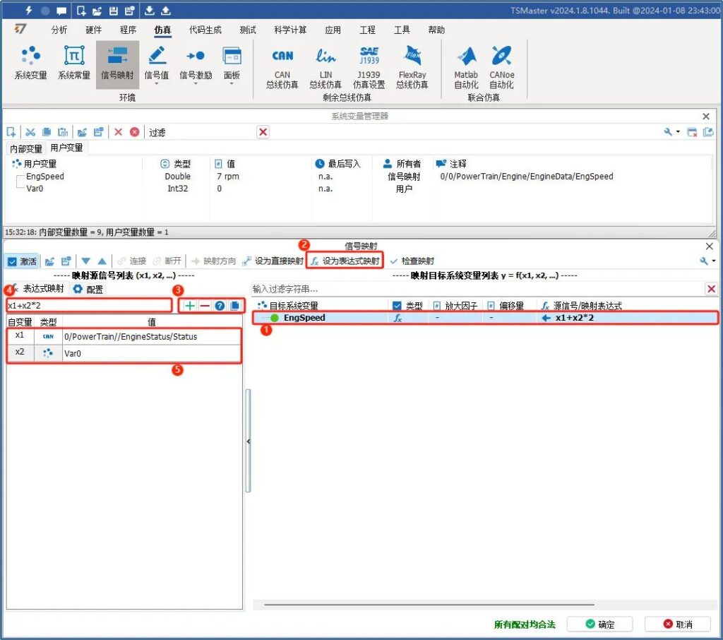
② Set to expression mapping
③ Click on the plus sign to add an independent variable

: Add independent variables

: Deletion of independent variables

: See help for arbitrary expressions

: C code that copies the current expression mapping

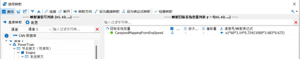
④ Edit calculation method expression

⑤ Assign values to the independent variables in the calculation expression. The independent variables can be selected from constants, system variables, FlexRay signals, CAN signals, and LIN signals.


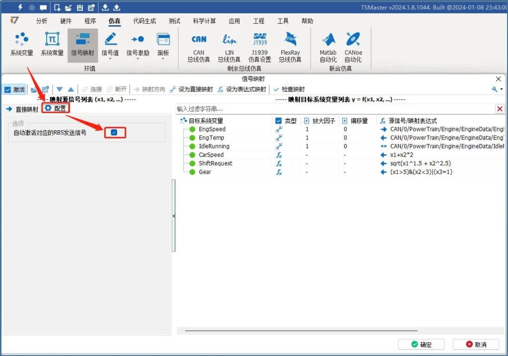
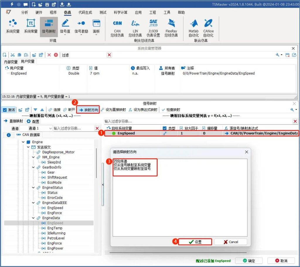
[Check mapping]:After completing the addition and configuration of the signal mapping list, you can choose to check the current mapping, which can avoid the situation of invalid mapping.

[Configuration]:Automatically activate the corresponding RBS transmit signal. The signals involved in the mapping list will be sent as RBS emulation after checking the box, as in Figure 6.

Figure 6

The configured list of mapped signals can be saved and imported in a configuration file, as in Figure 7.


[Configuration File Save]:You can export the current mapping pair configuration locally after the signal mapping pair configuration is complete.

[Configuration File Import]:You can export the current signal mapping list to an .ini file.

Figure 7

III. Example of signal mapping conversion

There is a common conversion relationship between car speed and engine speed calculation, car speed (km / h) = engine speed x 60 x 3.14 x tire diameter / (1000 X main gear ratio x corresponding gear ratio). Usually the tire diameter, the main gear ratio, the corresponding gear ratio can be found through the car manual, and then through the known engine speed, the use of signal mapping to calculate the car's speed, that is: car speed CarSpeed = engine speed * 60 * 3.14 * 0.724 / (1000 * 3.683 * 0.672).


Create the target system variable "CarspeedMappingFromEngSpeed" in TSMaster's signal mapping, set it as expression mapping, and bind it to the engine speed of the car, as shown in Figure 8.


CarspeedMappingFromEngSpeed = x1*60*3.14*0.724/(1000*3.683*0.672)

Figure 8

After configuring the signal mapping expression, you can modify the value of EngSpeed to 1000 rpm, and after signal mapping, you can automatically calculate the speed to 55.1 km/h, as shown in Figure 9.

Figure 9

Similarly, continue to modify the value of EngSpeed to 2000 rpm, after signal mapping, the speed can be automatically calculated to be about 110.2 km/h, as shown in Figure 10.

Figure 10

The above is the operation flow and example of signal mapping module. The system variables mapped by signal mapping can be directly accessed and used by our panel module, signal test module, signal comparison module, C applet, graphic module, etc. Signal mapping is a member of interoperability of modules in TSMaster, and the reasonable use of the signal mapping module can effectively improve the development efficiency of TSMaster-based projects. Signal Mapping is a member of our TSMaster to realize module interoperability.

发表回复