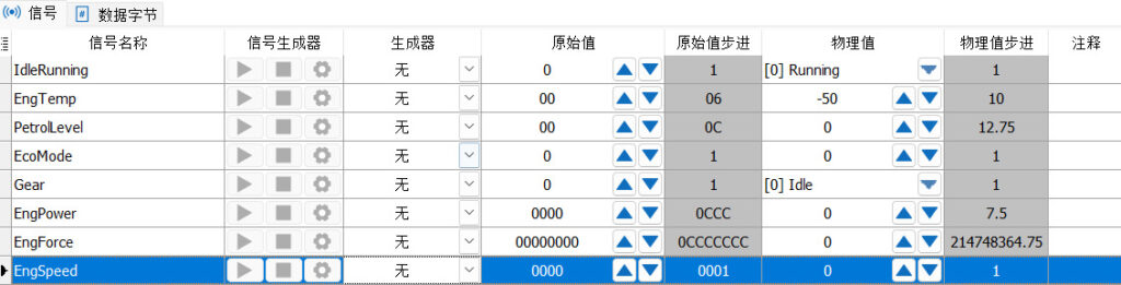
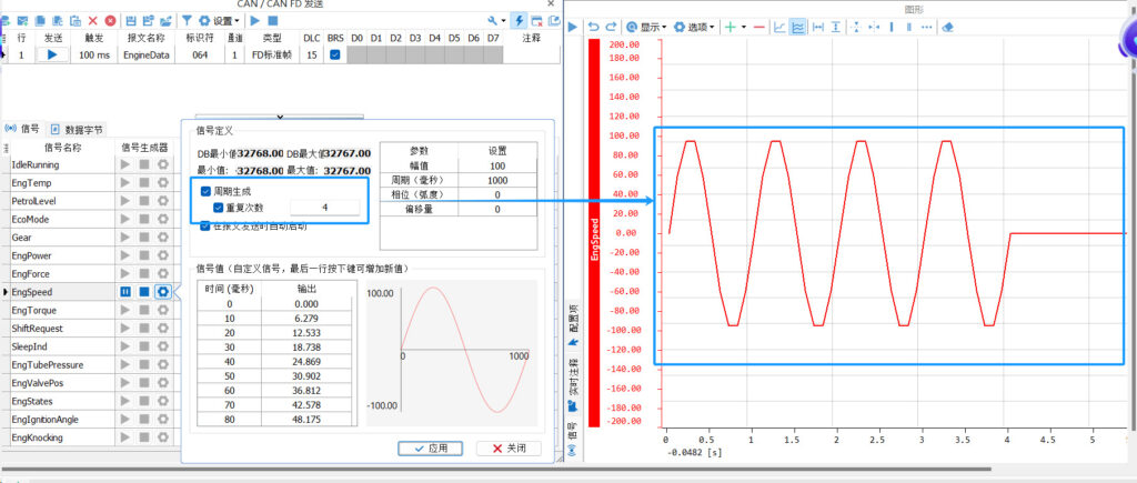
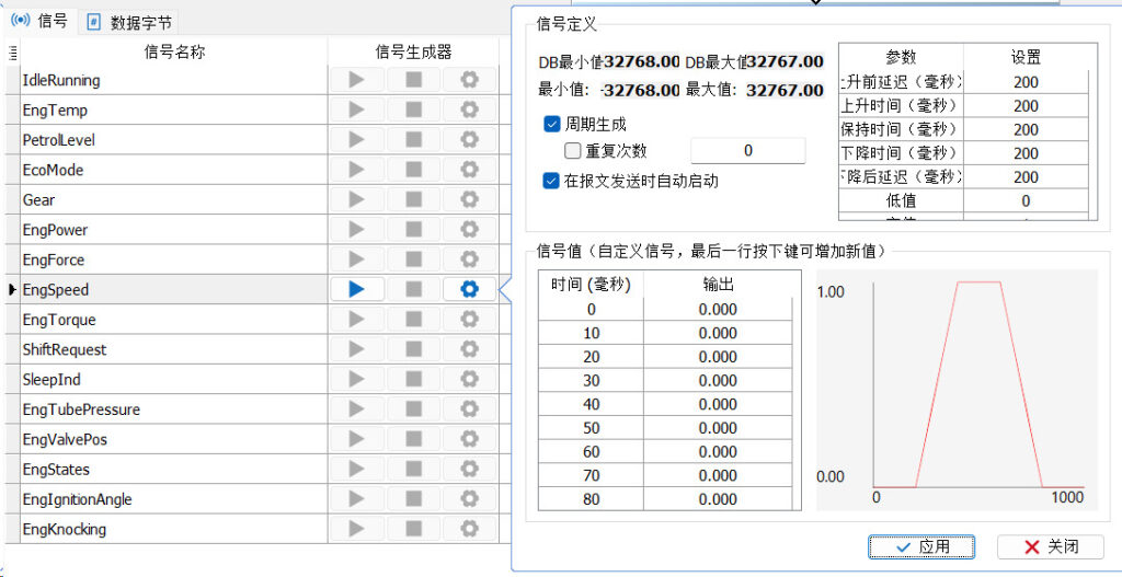
You are currently viewing 干货分享 | TSMaster报文发送的信号生成器操作说明

Sharing | Signal Generator Operation Instructions for TSMaster Message Delivery

overviewPreface

The Signal Generator function is the message sending module in TSMaster Analytics. The Signal Generator is used to send and configure the value change behavior of each CAN/LIN signal, in short, it is a function that allows you to control and adjust the value of the CAN/LIN signal. There are 8 types of signal generators we can choose from, and today we focus on sharing with you about how to use the 8 types of TSMaster signal generators.

Keywords in this paper: signal generator, sine, ramp pulse, value range, switching, random, custom, system variable

Table of Contents for this article
In the CAN/CAN FD Transmit window, when a message from the database is created, it can be selected to assign a signal generator to the signal. In this case, the signal generator has three buttons, as shown in Figure 1:
Figure 1: Start Pause Stop button of the signal generator

Start button: the current signal uses the generator to generate the value, after clicking this button the button will change to "pause button"

Pause button: When this button is clicked, the current CAN/LIN generator is paused and the button changes back to the "Start button".

Stop Button: Click this button to stop the current CAN/LIN generator operation.

No signal generator type

None means that there is no CAN/LIN signal generator available. The signal value in the sent CAN/LIN message depends on the physical value set in the "Physical value" on the right. This is shown in Figure 2 below:

Figure 2: Generator type is none

Signal Generator Type Sine

When Sine is selected this signal is defined as in Figure 3: The selected CAN/LIN signal will generate a sinusoidal waveform in a rising-falling- time series.

Figure 3: Sine of generator type

The interface is described below:

(1) DB Min and Max: The minimum and maximum values defined in the database.
(2) Physical Minimum and Maximum: the physical minimum and maximum values that a signal can reach.
(3) Cycle Generation: When cycle generation is checked, the generator can restart itself. The specific effect can be seen in the figure below, using the graphic function as an example, such as Figure 4 is an example of unchecked cycle generation, is only generated a waveform. As Figure 5 is an example with cycle generation checked, you can see that it has been generating continuously.

Figure 4: Graph generated by unchecked cycle generation
Figure 5: Graph generated by tick-period generation

(4) Repeat Count: The number of restarts generated periodically. If not specified, the number of restart cycles is unlimited. The number of repetitions depends on the number of times you fill in, and whether this setting takes effect depends on whether the "Cycle Generation" function is activated or not. As an example, look at figure 6 below and use the graphic function. If you fill in the number of repetitions 4 times, then 4 sine waveforms will be generated.

Figure 6

(5) Start automatically when the message is sent: when this function is checked, the signal generator of this signal will start automatically when the message is sent.

(6) Signal Value Table: The Signal Value Table defines the physical value of each signal in milliseconds versus time. The table is read-only except for custom signal generators. If the type of signal generator is customized type, you can press the key to customize the value, please refer to the chapter of "Customizing Signal Generator Type" for details.

(7) Parameter list: The signal graph depends on the parameters defined in this table, as shown in Fig. 7 below, and modifications can be made to the amplitude, period (milliseconds), phase (radians), and offset.

Figure 7

(8) Signal Waveform Preview: You can preview the waveform in time value view here.

Signal Generator Type of Ramp Pulse

The ramp pulse is set up as shown in Figure 8 below and the selected CAN/LIN signal will be generated in a rise-hold-fall-delay time sequence. The high value, low value and each time period can be modified.

Figure 8: Setting of ramp pulse of generator

Ramp Pulse - Parameter List

The signal graph depends on the parameters defined in this table, as shown in Figure 9 below, and can be modified for rise time, hold time, fall time, delay time after fall, low value, and high value.

Figure 9: List of parameters

Value range of signal generator types

The value range generator traverses the signal values in an "up", "down" and "alternate" manner, and the value ranges are set as shown in Figure 10 below.

Figure 10: Setting of the value range of the generator

Value range - parameter list

The signal graph depends on the parameters defined in this table, as shown in Figure 11, and can be modified in terms of step amount, hold time, minimum value, maximum value, and direction.

Figure 11

Signal Generator Type Switching

The switched signal value is switched between low and high, and the user can specify the low and high values. The settings for switching are shown in Figure 12 below.

Figure 12: Setting of Generator Switch

Toggle-Parameter List

The signal graph depends on the parameters defined in this table, as shown in Figure 13, and can be modified for low and high values.

Figure 13

Signal Generator Type Random

The Random Signal Generator outputs a random signal value, and you can specify the low and high values of the random range. The random settings are shown in Figure 14 below.

Figure 14: Randomized settings of the generator

Randomized values-parameter list

The signal graph depends on the parameters defined in this table, as shown in Figure 15, and can be modified for low and high values.

Figure 15

Signal Generator Type Customization

Users can customize the signal values in the Custom Builder, as well as import and export .sig files, with customized settings as shown in Figure 16 below.

Figure 16: Customized settings of the generator

Customization - Parameter List

Sampling time can be set in milliseconds.

Customization - Signal Value Table

To add a new value to the table, press the Down key; to insert a new value before the selected value in the table, press the Insert key, as set up in Figure 17.

Note: The time series in the table must be in ascending order, otherwise the generator will stop at the wrong time.

Figure 17: Signal value table for customization

Customize-Import Keys

Users can import externally defined signal waveforms. The extension of the waveform data file should be "*.sig", as in Figure 18.

Figure 18: Importing a "*.sig" file

The "*.sig" file format is shown in Figure 19 below:

Figure 19

Row 1: Interpolation method, currently only linear interpolation is supported.
Line 2: Sample rate in milliseconds.
Line 3: Delay time (milliseconds).
Line 4: Signal name.
Row 5 and below: table data for defined signal values separated by the ";" character.

Customize-Export button

The export function of the signal generator will export the current table value to a "*.sig" file, as shown in Figure 20.

Figure 20: Export format as .sig

Signal Generator Types of System Variables

The user associates system variables, and signal changes follow changes in the system variables. The system variables can come from user variables or internal TSMaster variables such as those created by C applets, diagnostic generated variables, calibration variables, etc.

System Variables-Parameter List

The signal graph depends on the parameters defined in this table, and modifications can be made to the associated system variable values and sampling period values, as shown in Figure 21.

Figure 21

Example:The Engspeed signal is associated with Var0 of the system variable, as shown in Figure 22.

Figure 22: Generator's system variable settings associated with Var0

When Var0 increases by 1 every 100ms and the value of Engspeed follows by 1 every 100ms, the graph changes as in Figure 23.

Figure 23: Engspeed value increases by 1 every 100ms

发表回复