
overviewPreface
As you know, the J1939 protocol is a set of standards defined by the Society of Automotive Engineers (SAE).The J1939 standard is used for heavy duty vehicles such as trucks, buses and mobile hydraulics. Most of today's vehicles have ECU communication via CAN. However, the CAN bus only provides the basis for communication (like a telephone), but does not provide the "language" of conversation for more complex operations. So in most large vehicles, the "language" is the J1939 standard defined by SAE.
Today we continue to introduce the new feature of TSMaster - J1939 multi-frame message sending and receiving. This feature belongs to the J1939 advanced features, need license authorization, specific operational requirements can contact us.
I. J1939 Functional Use
Use of J1939 functionality
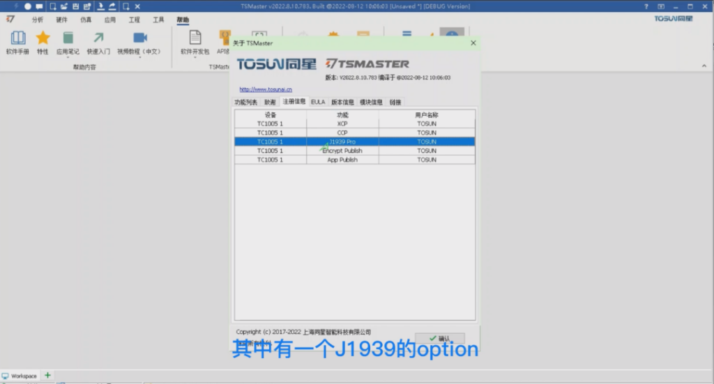
Let's assume that we already have hardware with license, take TC1005 as an example, connect the application after selecting the hardware channel, then open the about window, you can see the list of those who have license. One of them is the OPTION of J1939, the use of this function is described next.
> First, open the installation directory of TSMaster, enter the demo folder, and find the database file of the example database J1939ILDemo. We drag it into TSMaster, this process of dragging in needs to be done when the program is disconnected, you can see that there are four frames of messages inside this database, and its PGNs are EF00, EF00, FF02 and FF01 respectively.
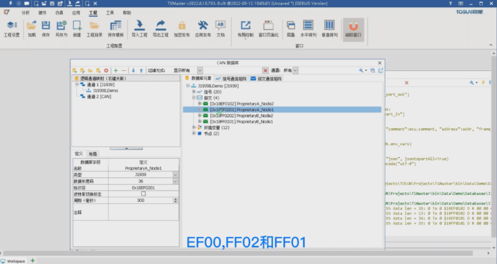
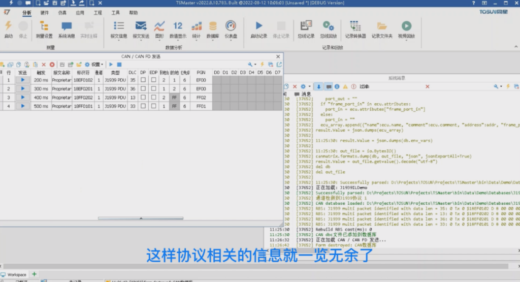
> The first two of these frames are point-to-point multiframes, which are sent from node 2 to 1 and 1 to 2; the last two are broadcasts, which are broadcasts from address 2 and broadcasts from address 1. Take the first frame as an example, his DLC = 35 bytes, which means that this signal can be arranged arbitrarily inside this 35 times 8, that is, 280 positions. Then sgn1~4 in the message are simulating this situation. If you want to send these messages, we can directly use the transmit window, we open the CAN Transmit window, click on the upper left corner of the button from the database, select the four frames of the message that we just saw, and then switch the view to J1939, so that the protocol-related information at a glance.
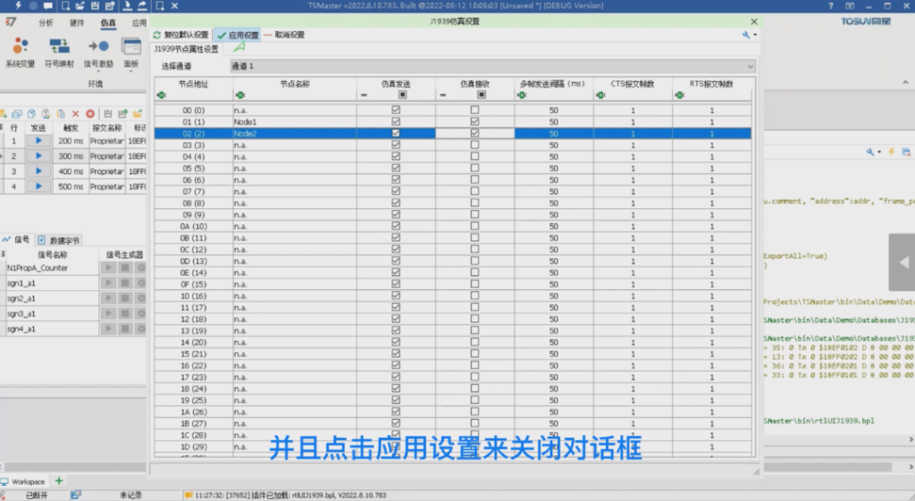
The first two are point-to-point and the last two are broadcast, which can be seen from the destination address. For broadcast messages, the sending node only needs to send itself. For the first two point-to-point messages, not only the sending node, but also the receiving node needs to answer during the process in order to complete the whole sending process. Therefore, we need to activate the J1939 emulation node built-in TSMaster.
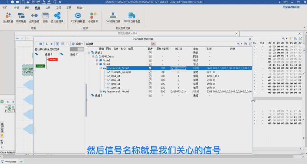
> Next, we come to the simulation, J1939 simulation configuration dialog box, you can see the node 1 and 2, respectively, labeled as Node1 and Node2, all the nodes are checked the simulation of the send function, but the simulation of the receive function is not checked by default. We can activate the two receive functions automatically by activating the rbs method, at the same time it can also be manually hooked, here we manually hooked, and click on Apply Settings to close the dialog box.
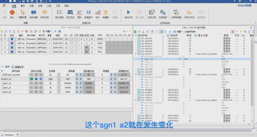
> At this point you can start the simulation, we press F5, and then open the trace window, then we activate the four nodes of the four messages to send, just click on send in turn. So in the middle of the trace window on the right you can see the reception of these 4 multiframe messages. Their DLCs are 35, 36, 13, and 33 on the right, and their default data segments are all 0 on the right.

> We can of course modify their data bytes to arbitrarily modify their data, then here you can see that this is the result of the modification we have just made, we can of course also be changed by way of the signal generator, for example, we select the first frame of the message, in this sgn1 a2 above the selection of sine, and then click on the configurations, we can change the peaks to a slightly larger, and then click on the application, click on startup Then we can change the peaks a little bit, click Apply, click Start, and at this point you can see that the sgn1 a2 is changing.
> Next you can open the graph window, drag this signal in, you can see the sine wave, of course the frequency of this sine wave is relatively low, this is because it is multi-frame, it takes 200 milliseconds to send a frame, so there are only 5 points in a second, we can also look through other windows, such as the numerical display.
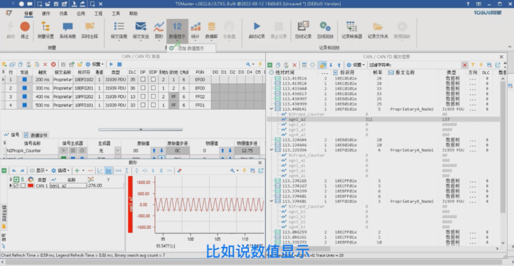
> Finally we open the value display, click on the add button here, we can select our signal, of course we can drag the signal in by dragging it, and then we can adjust the size of the window, so that the signal value can be displayed on it. We can also add the signals by means of a panel, but of course the panel needs to be designed, so first we need to stop the simulation, after stopping the simulation we can drag the signals into the panel, then start the simulation, and then start the sending of the telegrams, and then we can see that the signals can be displayed correctly in the measurement window.
II. J1939 series of API functions
J1939 A series of API functions
J1939 has a set of API functions, through this set of API can realize the J1939 signal reading and writing, message sending and a series of functions.
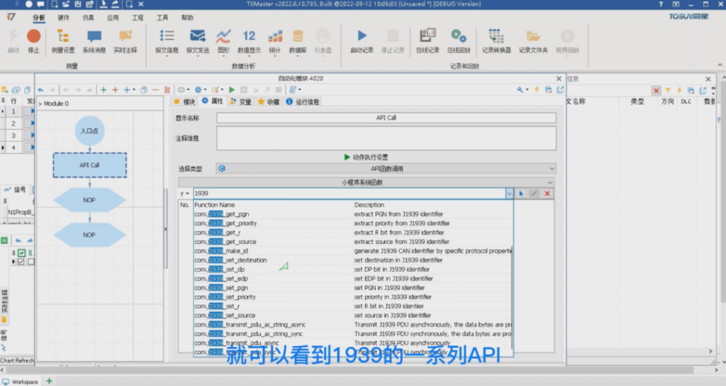
> We open an automation module and check the entry point and press enter to add a series of actions. Let's select the first action and set it to be an API function call, type 1939 into the filter and you'll see a list of APIs for 1939, including the get and set methods for 1939's identifiers, and the following methods for sending multi-frame messages. The get and set methods for identifiers are not described here, you can check the help file of the applet in the c-code editor, which has a detailed introduction, and you can also see the sample code on the right side. So this time we focus on the API for sending multiple frames in 1939.
> First of all, we can check 1939 Asynchronous Send API, then send is divided into synchronous and asynchronous two kinds, synchronous means that the program will go down after sending, asynchronous means that as long as the data will be pushed into the send buffer, the program can continue to go down, then no matter whether it is synchronous or asynchronous, but also divided into two types. One is sending without strings and the other is sending based on strings. String-based sending, his data is separated by commas, then both ways are supported by the automation module. Because in the automation module, the arrays are expressed as comma-separated strings, then we can choose an asynchronous send, function you can see that this function has seven input parameters.
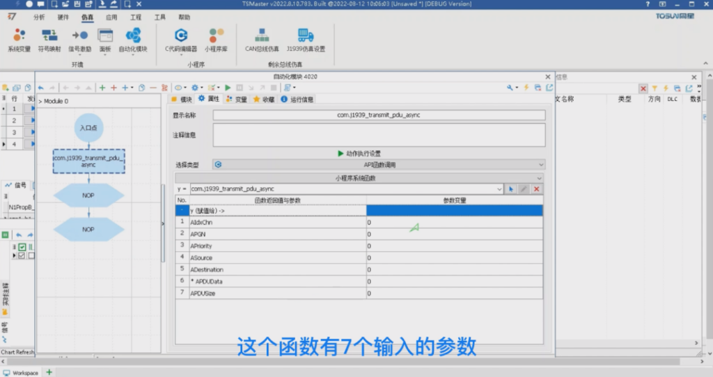
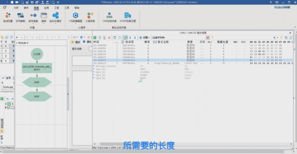
> Then the first parameter is the channel number, we can choose the constant, for example, channel1 then PGN, here we can enter. For example, we can choose broadcast, which is OxFF01 that we just saw, and then the priority is 6, the default source address is 2, and the destination address is 1, and then the PDU data we can fill in at will. For example, Ox11, and then we can copy this multiple copies, secret paste multiple copies, here the length is can be very long. His actual length is limited by the last parameter, so here we can keep the same with dbc, that is, 35, then we can start, press F9 to start sending or click on the send button, then you can send successfully.
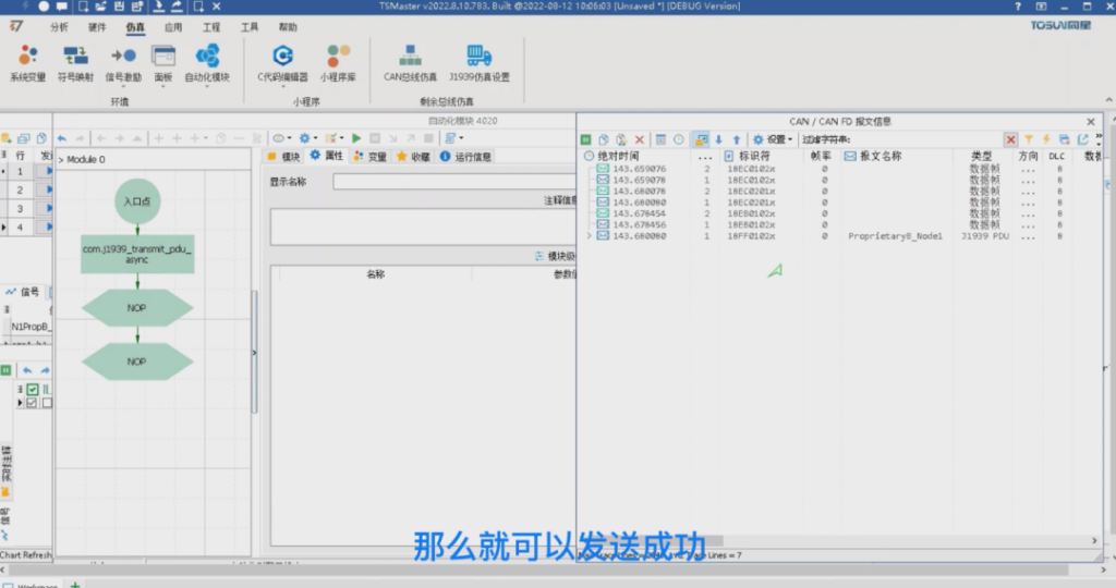
> We can see that the trace window shows exactly the same signal as we have set up, and at the end, if we say that there is not enough data, it will be filled with zeros. Then we can fill in more data and start sending again, so that the data length will be exactly what we need.
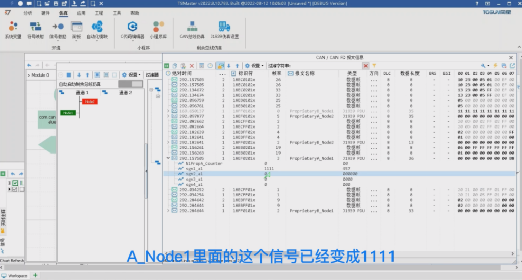
This is the original message sending method, if you need to modify the value of the signal inside the message, you need the rbs simulation engine to support, then we can click on the CAN bus simulation window to simulate the behavior of the node, we activate the two nodes, and then the bus simulation is set to start automatically, this time you can see that the rbs is already in operation, and we get the same results as through the sending window. .
> Of course the sending window at this time is not supposed to start sending, back to the automation module, delete our original message sending action, set a new action derived from the function call, here we search for set Signal by address, through this function can be realized in the rbs signal arbitrary modification. Then here are two parameters, respectively, the signal address and value, then the signal address is the database address of the signal we need to send, we can just pick one for example, A_Node1 signal 1_a1, we can click to copy the database address, and then paste it here, and then his value we can modify at will, and then we can click to start, so this realizes the signal modification. We can see that the signal in A_Node1 has become 1111, which is the value we set, so this is the signal sent.
What should I do if I am hoping to receive a signal value?
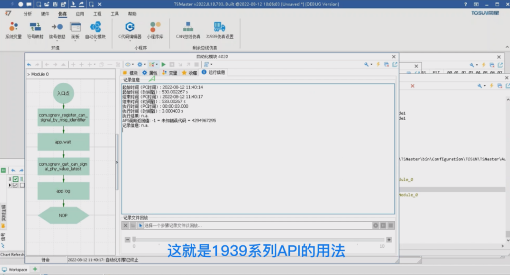
We can use the signal server method: still coming to the function call, deleting the send we just had, and then adding a couple more actions. We'll start by changing it to a function call and typing in SGN SRV, which is a series of functions for signal server.
> Then here we need a process, first we need to register the signal we care about, we need to use register_can_signal_by_message ID or name, we choose the message ID here, then we need to go to the rbs inside the copy this message ID, copy over the time you need to delete the x behind the string, so that this string is a valid hexadecimal value, the channel can still use the previous channel 1, then the signal name is the signal we care about. to make this string a valid hexadecimal value, the channel can still be channel 1 as before, and then the signal name is the signal we care about.
> For example, sgn1_a1, we ourselves directly input sgn1_a1, client ID is this function after the success of the registration of a handle to our program, we can create a new variable to store it, on the name of the ID on the line. This time directly can click on the local variable associated with our ID, then we can wait a while and then read the value of the signal, then this time you can call the wait function, such as waiting for a 3 seconds, and then followed by a reading process, the same used Signal server sgnsrv get_can_signal physical value. Finally through this method to get, get the physical value of the signal, then here you can also choose channel1 client ID to fill in the variable ID we just got, and then here is the output value, we can also use a variable to load, here you need to add is a double-type variable, value write a v on the line, and then in this place to choose v, and at the same time will also return the last timestamp, if you do not need, we fill in a default of 0 on the line or not fill.

> Then this time we can print out the value we read, this time we need to use the log function string, we can write the value of our variable v as a string, then log level, you can use a color, for example, green, and then we click on start, this time we first get the ID to wait, and then finally get the value to end, then we will look at each step of the We'll look at the results of each step. There is feedback here, here is the actual incoming parameter value, wait and then read the parameter value and then we can see the print out value is 111, is the value we set before, then we can change the value, for example, change to 12345, the value of the maximum is 2047, we set it to 2047, this time we just start the program again, we open the log, you can see that we get the same value as we set the value is the same. This is the use of 1939 series API.
About More
The above is the new features of TSMaster J1939 multi-frame message sending and receiving, we will see you in the next issue! (You can watch the video on our B-site for specific operation explanation)


